Automatic training
The initial set-up of the part is fully automatic using 6 images:
-
Empty feeder without part
-
Part in the centre of the feeder
-
Part in every feeder corner
This data is used to automatically set the training part and the free zones.
Information: This unique training concept ensures quick and uncomplicated commissioning. Fine-tuning is possible at any time at a later date.
Database with training images
New parts are trained via the database by acquiring 6 images.
The existing TeachIn can be viewed  for each position.
| Step | Description | Necessary for | |
|---|---|---|---|
|
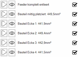
Feeder completely emptied | The image of the empty feeder is required for basic parts extraction during automatic training and for calculating the approximate allocation for the parts feeding. | Part distribution |
| Part placed in the centre | This image is used for the automatic training of the part contour and the first free zone. | Train part | |
| Part corner 1 | These images are used to determine the differences in area due to the perspective distortion of the lens at the edges. The average area is used to calculate the approximate occupancy. | Only required for determining the average part area. | |
| Part corner 2 | |||
| Part corner 3 | |||
| Part corner 4 |
Information: If an image already exists  , the feeder or the training part can be reset
 .
.
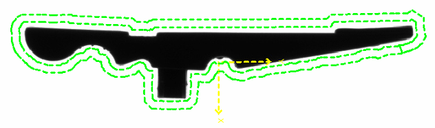
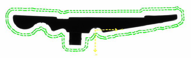
Important: During the training of the feeder area, the search area for the occupancy check must be set. Depending on the feeder size, the area should be set 5 - 15 mm away from the edge. This area is important for the calculation of the approximate occupancy and the parts feeding!
The image of the empty feeder is required for basic parts extraction during automatic training and for calculating the approximate allocation for the parts feeding.
-
Start training by clicking on
 .
.-
Set search area during training.

-
End the training process with
 .
.
-
-
If the training was successful, the line is marked with
.
This image is used for the automatic training of the part contour and the first clearance area.
-
Start training by clicking on
.-
Place the part manually in the marked area.
-
End the training process with
.
-
-
If the training was successful, the line is marked with
and the recognised area of the component is displayed in mm².
Information: If the contour of the part (green outline) is not extracted correctly, the detection sensitivity must be adjusted.
These images are used to determine the differences in area due to the perspective distortion of the lens at the edges. The average area is used to calculate the approximate occupancy.
-
Start training by clicking on
.-
Place the part manually in the marked area..
-
End the training process with
.
-
-
If the training was successful, the line is marked with
and the recognised area of the component is displayed in mm².
Information: If the contour of the part (green outline) is not extracted correctly, the detection sensitivity must be adjusted.
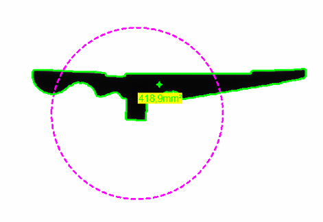
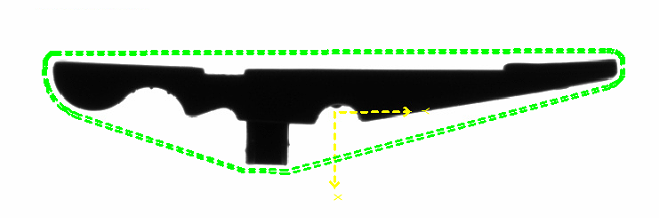
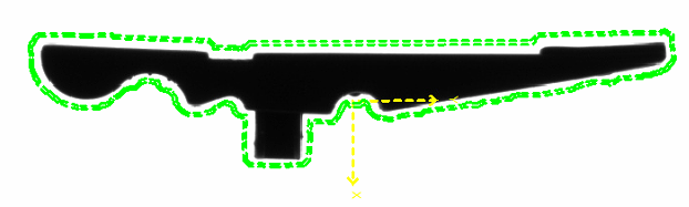
After successful training, the result looks something like this:
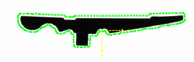
-
Yellow cross: The centre of gravity of the component is trained as a pick point, whereby the angle is always statically assumed to be 0°.
-
Green area: The free zone around the part is trained as 'free zone 1'. No other parts may be located in this area for the parts to be accepted as valid. This means that overlapping parts are recognised and excluded.
Information: The automatic training can be changed in the next step 'Train part'.
Information: If the contour of the part (green outline) is not extracted correctly, the detection sensitivity must be adjusted.
Train part
The upper menu bar is used to record new images and for reinspection after changing the tools:
| Function | Description | |
|---|---|---|
|
|
Start/stop live detection | Starts/stops permanent image recording and processing. This function is useful for testing detection stability. |

|
Capture single image and recognise parts | Takes a single image set ( backlight / front light depending on parameterisation) and carries out part detection. This function is used during parameterisation to test the detection. |

|
Update recognised positions (without image acquisition) | The part recognition is re-executed on the last captured image set and the data is updated. This function is used during parameterisation to test changes to the detection. |
The following functions are available:


| Complex contour | Simplified contour |
|---|---|
|
|
|
| Offset of the automatic free zone | Result |
|---|---|

|
|
|
|
|
|
|
|