Train part
In this step, the automatic training is refined and optimised. The user interface is organised as follows:
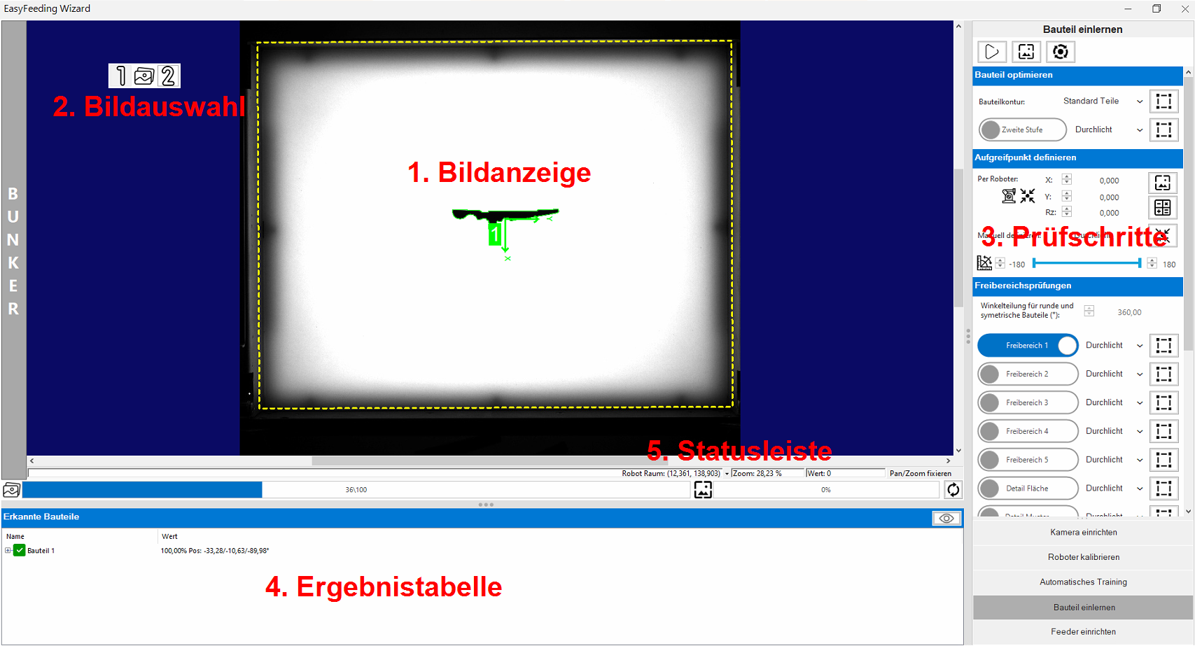 |
1. Image display | Displays the current image with its overlays. |
| 2. Image selection | If several images are available for selection, you can switch through the available images (front light, backlight, filter) using the image selection. | |
| 3. Inspection steps | The individual inspection steps can be activated, deactivated and parameterised in this bar. | |
| 4. Results table | The table provides an overview of the recognised candidates including a diagnosis if a component was rejected during the test. | |
| 5. Status bar | Status bar shows the current workspace with mouse coordinates and pixel brightness. |
The upper menu bar is used to record new images and for reinspection after changing the tools:
| Function | Description | |
|---|---|---|

|
Start/stop live detection | Starts/stops permanent image recording and processing. This function is useful for testing detection stability. |

|
Capture single image and recognise parts | Takes a single image set ( backlight / front light depending on parameterisation) and carries out part detection. This function is used during parameterisation to test the detection. |

|
Update recognised positions (without image acquisition) | The part recognition is re-executed on the last captured image set and the data is updated. This function is used during parameterisation to test changes to the detection. |
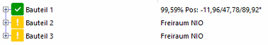
The results table is used to diagnose recognised candidates and helps to find the correct parameters.
| Image | Results | Description |
|---|---|---|
|
|
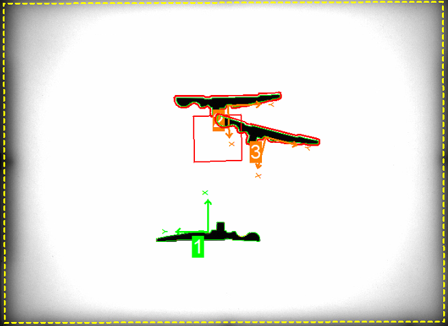
In this example, one part can be gripped and two parts are too close together. |
|
|
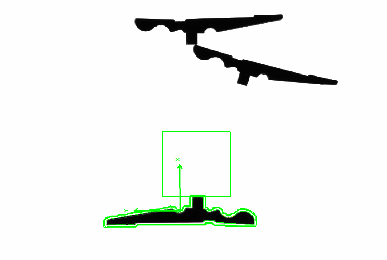
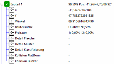
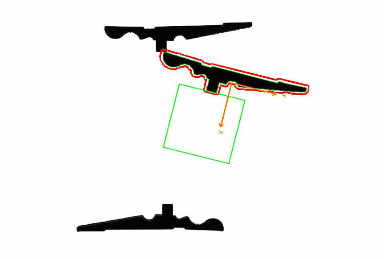
By clicking on part 1 in the table, the overlays in the image are reduced to part 1. This makes diagnosis easier if there are many parts on the feeder. By clicking on |
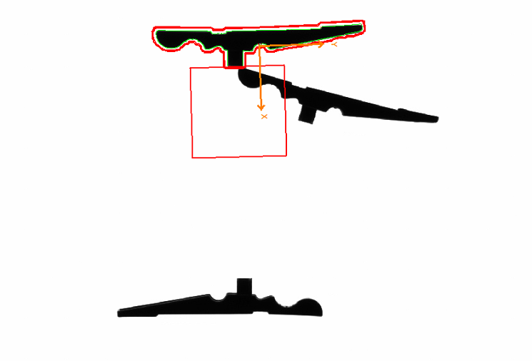
|
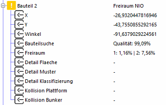
|
Part 2 shows two violated free zones with 1.16% and 7.56% defect area. |
|
|
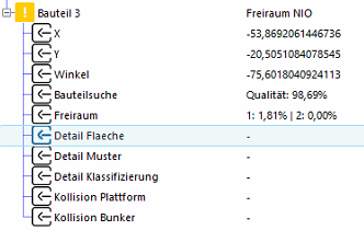
Part 3 shows a damaged free zone with a defect area of 1.81%. |

Information: While editing inspection regions, you can click on a part in the table to switch to its regions.
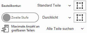
In this step, the process for searching the part contours can be optimised. There are 3 modes to choose from:
| Mode | Canditate search | Free zone and detailed inspection |
|---|---|---|
| Standard parts | -180° bis + 180° | Static when position is found |
| Round parts | 0° | Multiple: Position found + a multiple of the rotational division entered until the candidate is OK or 360° has been reached |
| Symmetrical parts | -180° bis + 180° |
Information: The search region of the part contour should also be adapted  . A reduction in the search area leads to a directly proportional decrease in part throughput
Important: The restriction of the picking area should be realised via the integrated collision check in order to keep the cycle time loss as low as possible.
Important: The position and angle correction using the second stage is an advanced parameter which is not necessary in 99% of cases and is helpful if the position of the component cannot be clearly found in the first stage. The second stage then carries out a fine search using an additional feature.
Information: With  it is possible to limit the number of parts to be gripped per detection run. This leads to an increase in the cycle time if there are a large number of parts on the feeder and a new image is forced with each run. The detection routine stops when the desired number of parts to be gripped is reached.
Parameter 'Part alignment (1st level)
The parameters for the free zones are displayed at the bottom of the inspection step bar:
| Function | Description | |
|---|---|---|

|
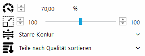
Minimum match of the contour in % | The percentage match of the part contour found must be ≥ this parameter for the candidate to be accepted. If this threshold is not met, the part is not accepted and no further inspection steps are performed |

|
Permitted size change of the part in % | The contour of the searched part may change in this area. A deviation from the standard (100%) is only recommended if necessary and must be tested well to avoid possible false positives. |

|
Characteristics of the part contour | 'Rigid contour': Accepts few deviations along the part contour. Standard for fixed objects. 'Bendable or tilted': Provides advantages if the parts can be bent or should be recognised in a tilted position. |

|
Sorting | Specifies the sorting of the recognised parts for the output: 'Sort parts by quality' or 'Sort parts by centre'. |
| Function | Description | |
|---|---|---|
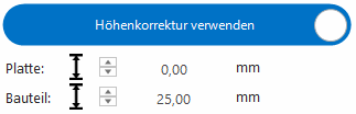
| Use height correction | Activates the automatic correction of the X/Y robot coordinates for parts with a different height to the robot calibration part. | |

|
Height of the plate | Height of the production plate used in millimeters (maximum dimension according to Asyril). |
|
|
Height of the part | Height of the part in millimeters . |
Calculate pick point by robot
The pick point is determined using our highly accurate BestPick process.
Information: This automatic system offers the highest possible accuracy with a short setup time.
-
The part is placed in the desired position in the robot gripper.
-
The robot places the part in the centre of the empty feeder to use the automatic adjustment.
-
Make sure that the component does not slip during storage.
-
-
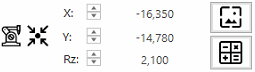
Enter the storage coordinates in the fields X, Y, Rz (in °).
-
Remove the robot from the camera field of view.
-
Take a new image
and check whether the component has been recognised correctly.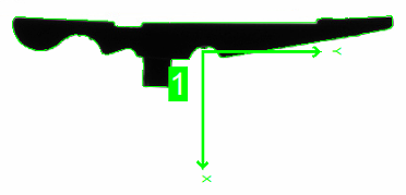
-
If the part is marked green, you can start the BestPick calculation
 . At the end, the image is updated and the new pick point is displayed.
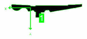
Information: The BestPick calculation can be automated via the fieldbus interface.
Define pick point manually
Information: For special cases, it makes sense to set the pick point manually.
The pick point can be set manually  . If backlight andfront light are used, the calculation can be carried out on either of the two images.
| Function | Description | |
|---|---|---|

|
Pick point | Pick point can be defined by X, Y and angle. |
|
|
Offset | The offset is an offset within the coordinate system of the pick-up point. This is useful if the pick point is to be offset geometrically. |

|
Detect pick point with circle | Detect the pick point once using a circle. The parameters are not saved permanently and are only saved once as a pick point. |

|
Detect pick point with edges | Detects the pick point once via the intersection of two edges. The parameters are not saved permanently and are only saved once as a pick point. |

|
Edit manually | The pick point and offset can be changed via the input field or graphically in the image using drag & drop. |
Limit pick angle
The pick point angle  can be limited and restricted. This function is helpful if the robot cannot pick up all gripping angles.
Information: The restriction of the pick angle leads to a directly proportional reduction in throughput.
Enables additional checks around the found part position:
-
Collision avoidance of the gripper interference contour with parts
-
Recognising touching or intersecting parts
Information: Each inspection can be carried out either in front light or backlight.
Information: The integrated symmetry support enables intelligent inspection of symmetrical or round parts.
Free zone 1 is created as a polygon path during automatic training and is intended to ensure that overlapping parts are recognised.
Free zones 2-5 are available for additional gripper clearance zones to ensure that the gripper does not collide with parts on the platform.
Teach-in process
-
Activate the desired region.
-
It is possible to switch between backlight and frontlight for each free zone.
-
Use
to change the region. -
If several parts are visible in the image, the desired part must be selected in the table during teach-in.
-
Confirm the region with
 and accept.
 -
Take a new image
and check whether the part has been recognised correctly.
Important: If several parts are visible in the image, the desired part must be selected in the table during teach-in.
Parameter
The parameters for the free zones are displayed at the bottom of the inspection step bar:
| Function | Description | |
|---|---|---|

|
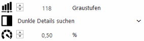
Threshold | Threshold value for recognising the error details. |

|
Colour of the details | 'Search for bright details': Counts all pixels in the area that are ≥ the threshold value . 'Search dark details' (default for transmitted light): Counts all pixels in the area that are ≤ the threshold value . |
|
|
Maximum permissible error size | The percentage of pixels found in the area must be smaller than the maximum permissible error. If this limit is violated, the candidate is rejected. |
Example
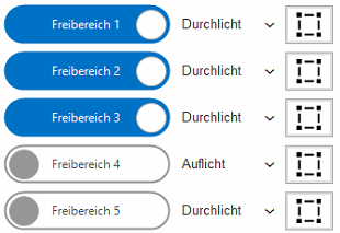
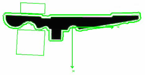
In this example, free zones 1, 2 and 3 are active:
-
Free zone 1: Check around the part for contact or overlap with other parts.
-
Free zone 2+3: Simulate the robot's two-finger gripper and check the collision of the gripper with other parts.
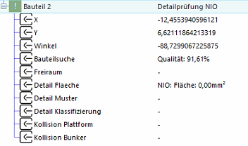
The detailed inspection is used to check the position of the part:
-
Is the part right or wrong. e.g. belly or back
-
If type mixing is possible, this can be recognised in the part inspection
The area check uses light or dark areas in the inspection area to detect the correct position.
Information: This inspection can be carried out either in frontlight or backlight.
Information: The integrated symmetry support enables intelligent inspection of symmetrical or round parts.
Teach-in process
-
Activate inspection step.

-
You can switch between backlight and frontlight for the inspection.
-
Use
to change the region. -
If several parts are visible in the image, the desired part must be selected in the table during teach-in.
-
Confirm the region with
and accept. -
Take a new image
and check whether the part has been recognised correctly.
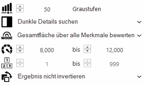
Parameter
The parameters for the free zones are displayed at the bottom of the inspection step bar:
| Function | Description | |
|---|---|---|
|
|
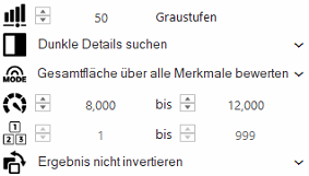
Threshold value | Threshold value for recognising the details. |
|
|
Colour of the details | 'Search for bright details': Counts all pixels in the area that are ≥ the threshold value . 'Search dark details' (default for transmitted light): Counts all pixels in the area that are ≤ the threshold value . |

|
Mode | 'Score all features separately': Checks the expected size of each area found and counts the number. 'Check total area across all features': Checks the total area of all areas found against the expected size. |
|
|
Expected size | The area of the details found (depending on the mode) must be within the expected size. |

|
Number of valid features | This option is only available in the mode 'Check all features separately' and checks whether the number of valid features is within the valid range. |

|
Invert result | This can be used to invert the inspection result in order to carry out an inverse inspection (if no characteristic is found, the inspection is OK). |
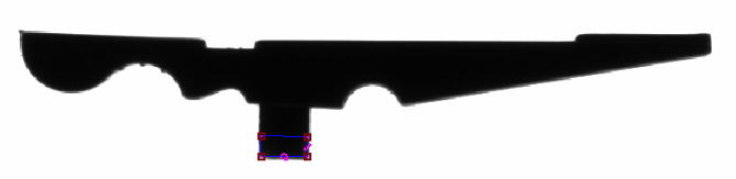
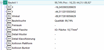
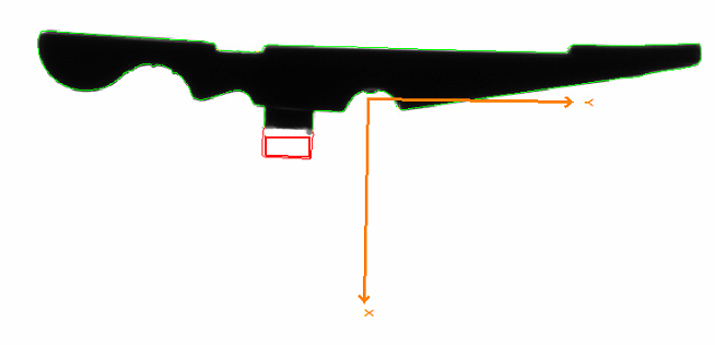
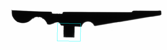
Example
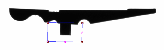
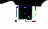
In this example, a feature of the part is checked for presence so that only the desired feature is used if different types are mixed, and the inspection region is placed on a unique feature.
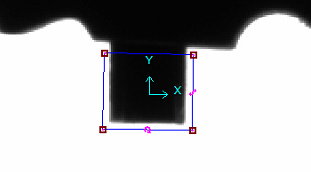
Region:
Parameter:
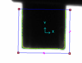
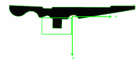
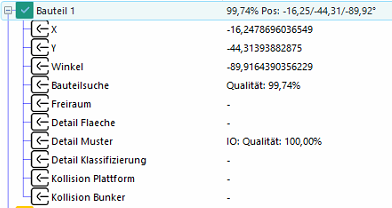
Correct type:
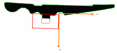
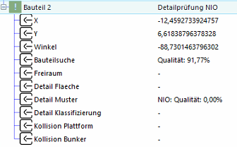
Wrong type:
The detailed inspection is used to check the position of the part:
-
Is the part right or wrong. e.g. belly or back
-
If type mixing is possible, this can be recognised in the part inspection
The pattern control uses a contour comparison in the inspection area to recognise the correct position.
Information: This inspection can be carried out either in front light or back light.
Information: The integrated symmetry support enables intelligent testing of symmetrical or round parts.
Teach-in process
-
Activate inspection step.

-
You can switch between backlight and frontlight for the inspection.
-
Use
to change the region. -
If several parts are visible in the image, the desired part must be selected in the table during teach-in.
-
Define the search area under 'Search'. Keep this as small as possible to avoid false positives.
-
Under 'Training'
-
With
 'Current image as training image', the current image is transferred to the training programme.
 -
Set the training area as narrow as possible.
-
Train with
the contour and check the markings. -
The contours can also be optimised using a mask
 .
.
-
-
Confirm the region with
and accept. -
Take a new image
and check whether the part has been recognised correctly.
Parameter
The parameters for the inspection are displayed in the lower area of the inspection steps bar:
| Function | Description | |
|---|---|---|
|
|
Minimum match of contour in % | The percentage match of the contour found must be ≥ this parameter for the inspection to be considered OK. |
|
|
Invert result | This can be used to invert the inspection result in order to carry out an inverse inspection (if no characteristic is found, the inspection is OK). |
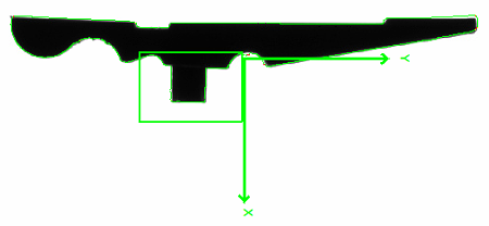
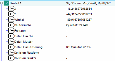
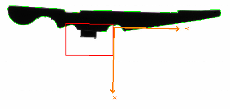
Example
In this example, a feature of the part is checked for presence so that only the desired feature is selected if different types are mixed. The test window was placed on a unique feature for this purpose.
Search region:
Train region:
Parameter:
Correct type:
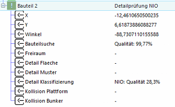
Wrong type:
The detailed inspection is used to check the position of the part:
-
Is the part right or wrong. e.g. belly or back
-
If type mixing is possible, this can be recognised in the part inspection
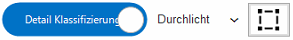
The classification uses an edge learning algorithm to recognise the correct position and is particularly suitable for distinguishing images with strong fluctuations or complex features.
Important: Classification is possible from EasySightPro 11.0 for an additional charge.
Information: This inspection can be carried out either in front light or back light.
Information: The integrated symmetry support enables intelligent inspection of symmetrical or round parts.
Teach-in process
-
Activate inspection step.
-
You can switch between back light and front light for the inspection.
-
The training region can be changed under Training with
.-
The training area corresponds to the search region in the process
-
Every change leads to a reset of the training
-
-
Confirm the region with
and accept. -
Next, place several parts in the correct position.
-
Take a new image
and check whether the part has been recognised correctly. -
Classify the parts in the table as OK
 with the right mouse button.
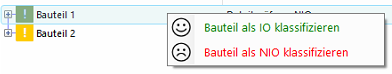
-
Next, place several parts in the wrong positions.
-
Take a new image
and check whether the part has been recognised correctly. -
Classify the parts in the table as NOK
 with the right mouse button.
-
Take a new image
and check whether the part has been recognised correctly.
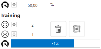
Important: At least two IO and 2 NIO parts are required for stable detection.
Parameter
The parameters for the inspection are displayed in the lower area of the inspection steps bar:
| Function | Description | |
|---|---|---|
|
|
Minimum match of classification in % | The percentage match of the classification must be ≥ this parameter for the inspection to be considered OK. |
|
|
Number of OK images | Anzahl an guten Bildern in der Trainingsdatenbank. |
|
|
Number of NOK images | Anzahl an schlechten Bildern in der Trainingsdatenbank. |
|
|
Quality of the model | Quality of the trained model. This scale makes the difference between the OK and NOK images visible in the database. |

|
Delete training images | Deletes all images from the training database so that it can be rebuilt. |

|
Open AI Training | Opens the AI training tool in expert mode. |
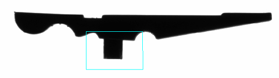
Example
In this example, a feature of the part is checked for presence so that only the desired feature is selected if different types are mixed. The inspection area was placed on a unique feature for this purpose.
Train region:
Parameter:
Correct type:
Wrong type:
The collision check takes into account the collision contours of the gripper and checks these against
-
the edges of the platform
-
the contour of the hopper
Important: As the interference contour of the bunker is higher than that of the platform, the interference contours for both levels must be defined separately!
Information: The integrated inspection of the gripper against the interfering contours minimises the cycle time loss and optimises the output of the overall system.
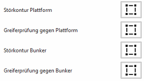
Teach-in process
-
Activate inspection step.

-
Define
and accept 'Check contour platform' in the collision check parameters.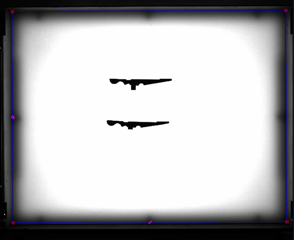
-
Define
and accept 'Gripper check against platform' in the collision check parameters.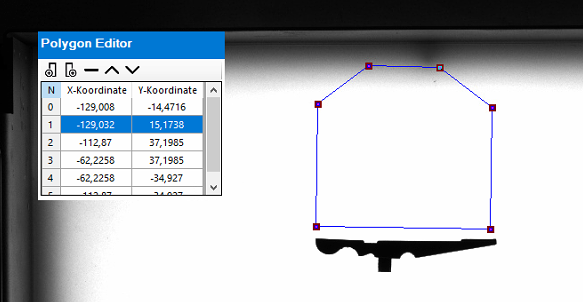
-
Define
and accept 'Check contour bunker' in the collision check parameters.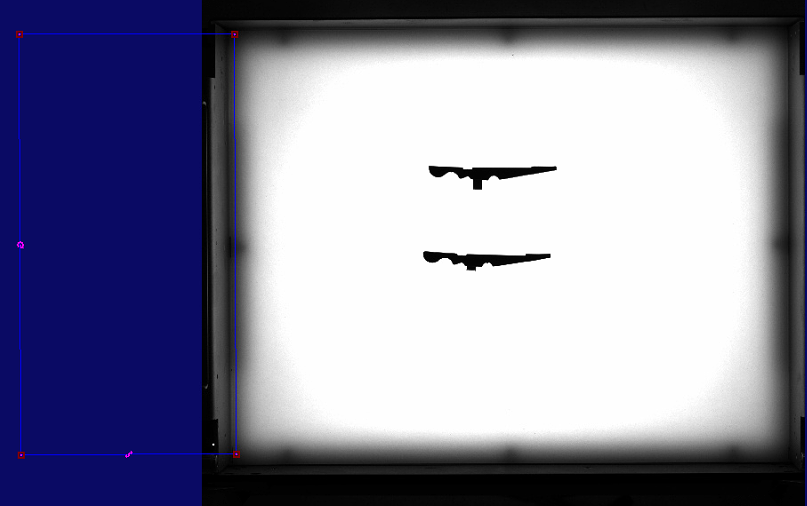
-
Define
and accept 'Gripper check against hopper' in the collision check parameters.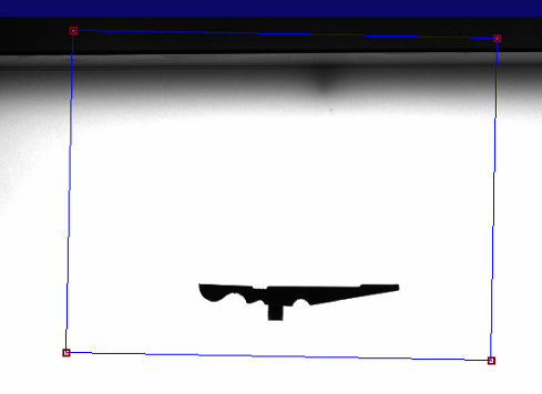
-
Take a new image
and check whether the part has been recognised correctly.
Parameter
The parameters for the inspection are displayed at the bottom of the inspection step bar:
| Function | Description |
|---|---|
| Interference contour platform | Interfering contour of the platform in the image. Here, the area should be drawn approximately in the edge area from the plate to the edge of the container. |
| Gripper check against platform | Interfering contour of the gripper at the level of the platform edge. |
| Interference contour hopper | Interfering contour of the bunker in the image. For safety reasons, it is recommended that these are slightly further into the image to compensate for the perspective distortions of the lens in this area. |
| Gripper check against hopper | Interfering contour of the gripper at the height of the bunker. |
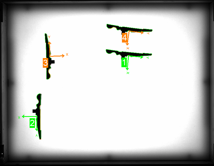
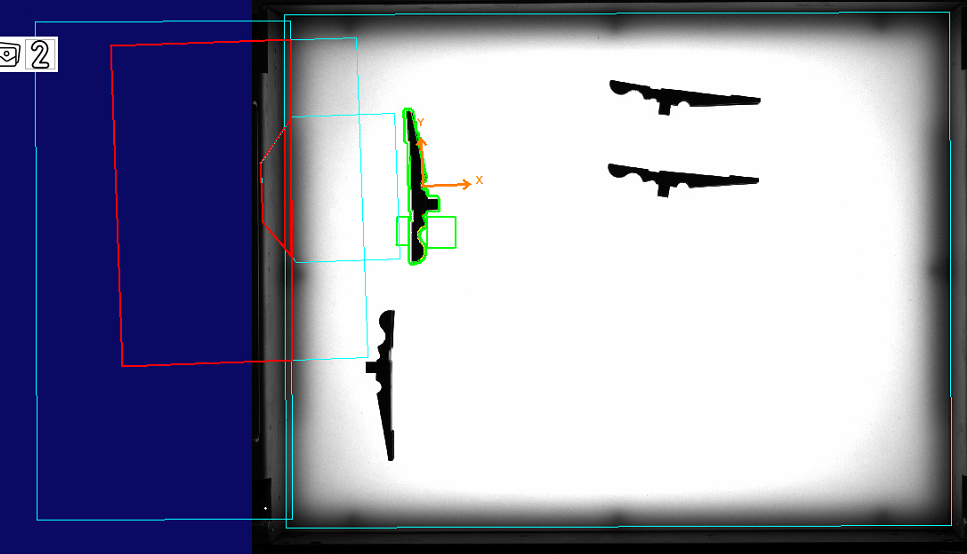
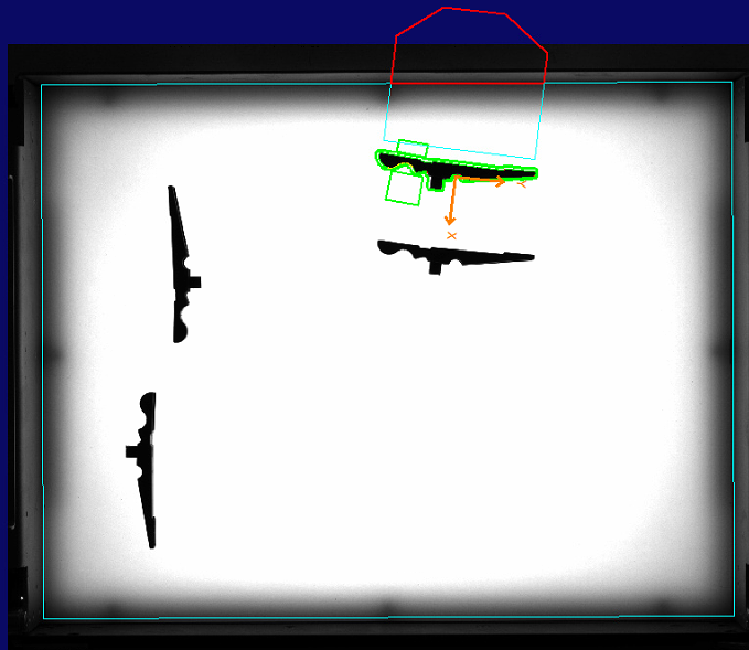
Example
In this example, 2 parts are reachable and 2 parts have a collision with the platform and the hopper.
Interference contour platform:
Hopper interference contour:
Results:
| Image | Result | Description |
|---|---|---|
|
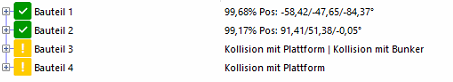
|
In this example, two parts are reachable and two parts have a collision with the interfering contours |
|
|
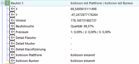
Part 3 collides with the platform and the hopper. A secure grip is therefore not possible. |
|
|
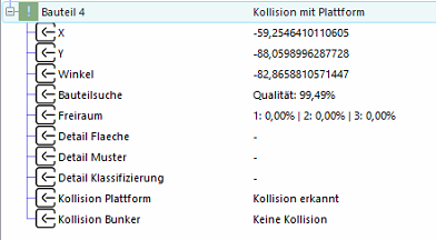
Part 3 collides with platform . A secure grip is therefore not possible. |