Calibrate robot
The aim of hand-eye calibration is to transfer the X and Y coordinates of the recognised parts from the camera coordinate system to the robot coordinate system. Thanks to the calibration, the robot coordinate system is transferred directly to the EasyFeeder station and all coordinates are output as robot coordinates.
Information: Robot calibration is performed globally and applies to all inspection programmes!
Important: The robot's coordinate system must be aligned with the plane of the surface of the Asycube plate.
Information: The reproducible positioning of the calibration part is important for the quality of the calibration!
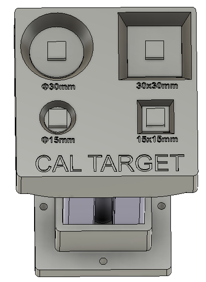
Use a part with the simplest possible contours (rectangle, square, circle) for calibration, as production parts are often not ideal for calibration.
-
Simple contours (rectangle, square, circle).
-
Height should correspond to the thickness of the part to be gripped.
-
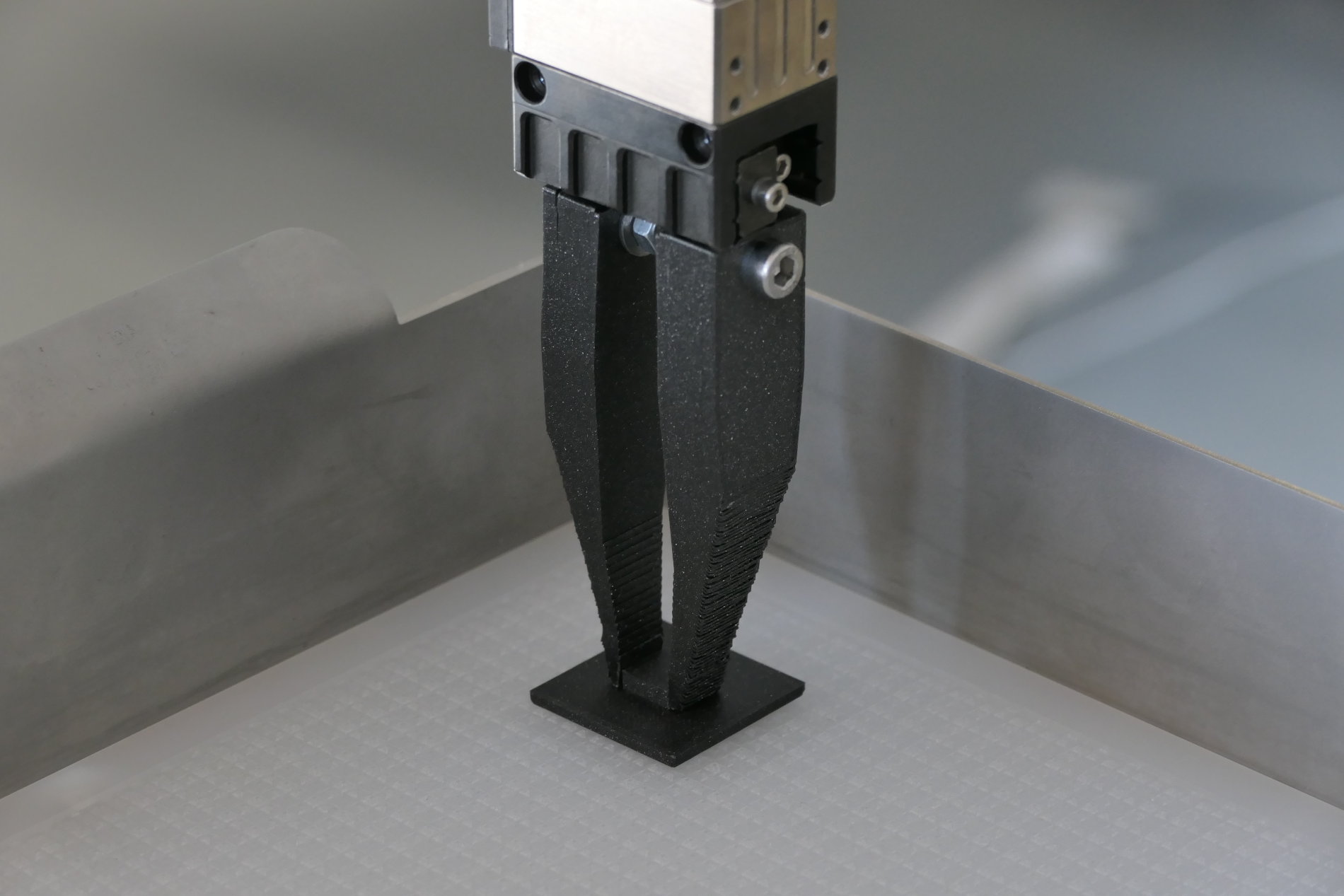
The calibration part must be reproducibly grippable. Ideally, the calibration part should be centred in the gripper.
-
The calibration part must not slip when it is placed down, as this would impair the quality of the calibration.
-
If the calibration is carried out with your own gripper, please note the possible differences in the TCP of the grippers.
Examples:
The coordinate system of the tool is positioned on the tool centre point (TCP). The TCP position corresponds to the position at which you want to grip the component:
-
Finger gripper: Positioning of the TCP at the point at which the gripper will grip the part.
-
Vacuum gripper: Positioning of the TCP at the end of the gripper.
Menu
Information: If no robot is available at the time of setup, the robot can be skipped using "Demo calibration". This involves inserting 4 simulated coordinate pairs into the calibration in order to simulate the calibration. This enables part training and feeder setup without a robot.
Important: The "demo calibration"  is not a substitute for calibration with the robot. Robot calibration is mandatory for productive operation.
Teach-in calibration part contour
-
Place the calibration part with the robot in the centre of the feeder surface.
Information: Please note that the angle of the part should always be 0° during calibration, as the calibration only works with X and Y coordinates.
-
Take a new image with
 .
. -
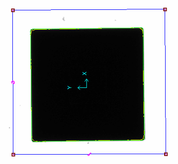
Use
 to train the contour of the calibration part and set up the search region.
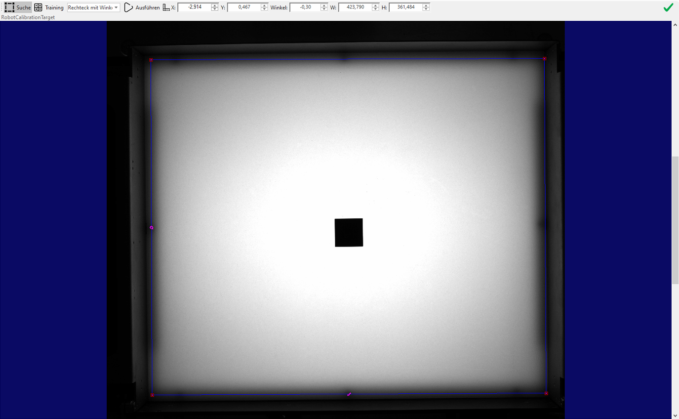
-
The search region for the calibration is defined under Search
. This area is used to search for the part during the calibration process -
The calibration part is trained under Training

-
Keep the search region as close as possible around the part.
-
Centre the centre point with "Centre in window"

-
The training process is performed with "Execute"
 and the trained contours are displayed in the image.
-
-
The contour training can be ended with
 .
. -
Take a new image
and check whether the part has been recognised correctly.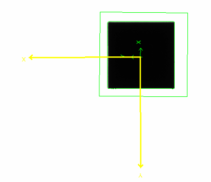
-
If the picking point displayed does not match the robot, it can be moved using "Change picking point"
 .
. -
If the height correction for parts is used, the height
 of the calibration part must also be entered in millimeters.
Optional steps when using height correction
Information: If the cross of the part recognition does not correspond 1:1 with the robot point, this is taken into account in one of the next steps in the picking point calculation.
Procedure for (manual) calibration
Calibration can be performed manually using the wizard or via the communication interfaces (TCP/IP or Feldbus).
Calibration must be performed using at least 4 points that are as far apart as possible. The more points used, the better the quality of the calibration.
-
Delete existing calibration

These steps must be performed for each calibration point:
-
Pick up the calibration part again with the robot
-
Place the calibration part on the feeder
-
Ensure sufficient distance from the edge and avoid any contact
-
Always place the part at the trained angle
-
Make sure that the part does not slip when you put it down
-
-
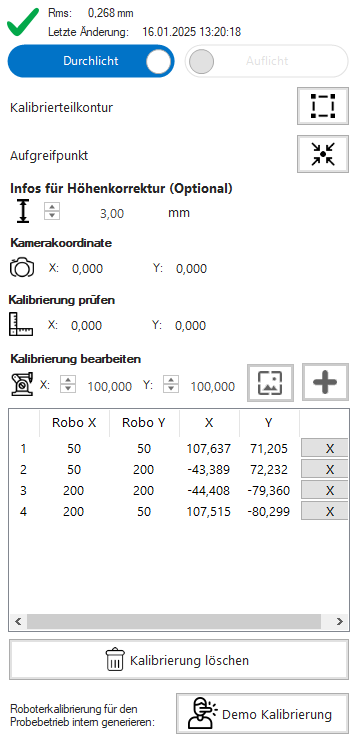
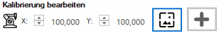
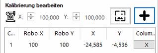
Enter part coordinates under "Edit calibration"

-
Move robot to camera field of view
-
Take a new image
-
Check detection. The camera symbol
 should be highlighted in green.
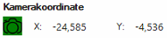
-
Add robot/camera coordinate pair to the list

-
Repeat this process for at least 4 points.
Information: From the fourth point onwards, the calibration is calculated and saved, provided it is valid. The lower the RMS error (Unit: Millimetre) displayed, the better the quality of the calibration.
Important: If the maximum RMS error is exceeded, there is a difference between the robot and camera coordinates. In such a case, it is recommended to delete the calibration and perform it again.