Cognex DS925 3D Scanner
Operating the sensor in EasySightPro®
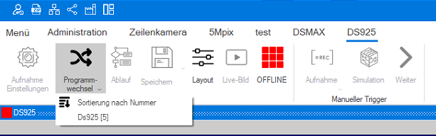
To inspect the scanner images, the station is assigned to the sensor and the corresponding program is selected.
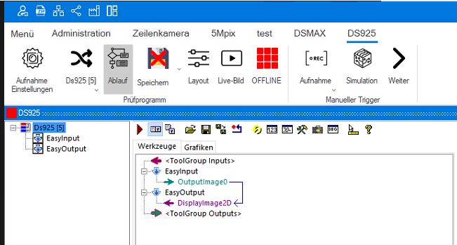
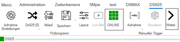
The program will now open the sequence:
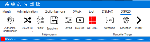
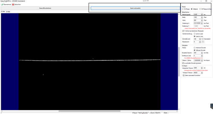
Now the sensor can be set up. To do this, we start the setup wizard by clicking on the live image. The sensor must be offline for this.
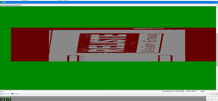
First, the test object should be brought into the measuring range of the sensor with the continuous exposure. To do this, the Brightness mode is selected and the Start continuous button is selected. Now the sensor measures while the object is brought into the image. Note the DS925's working distance of 66mm +/- 12.5mm- and the field of view width of 25mm. After we see the object cleanly as an edge in the image we select the exposure time. This should be high enough to see a nice edge without overexposing and thus over-illuminating the edge in the image (see image below).
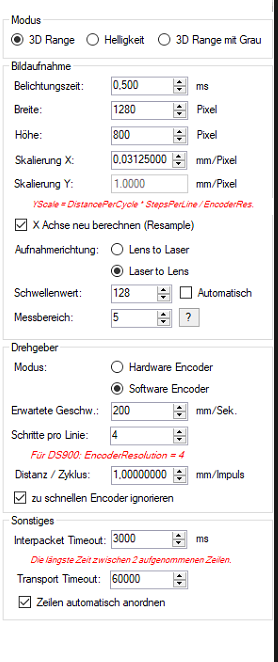
In the settings, the image capture mode is set first:
3D Range creates a separate
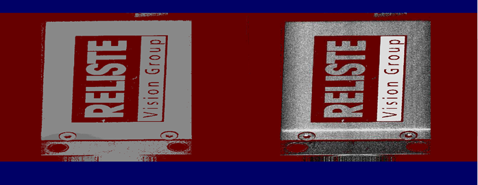
3D image and 2D image.Brightness creates an edge in 2D (see above).
3D Range with Gray creates a composite image.
3D Range with gray in 2D display
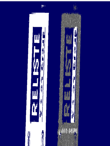
3D Range with gray in 3D display
Now the parameters for image acquisition can be set.
Width: Determines the scan width of the sensor. The maximum is 1280 pixels.
Height: Determines the length of the scan.
Scale X: Results from the width of the scan and the size of the image width in mm.
Can be calculated automatically by the system if the selection Recalculate X axis (Resample) is selected.
Scaling Y: Is calculated according to the formula below. With software encoders, the system takes over the calculation.

Now the scanning direction is set. Here the direction of movement of the parts in relation to the scanner is set. So either the parts move from the laser to the lens or vice versa.
The threshold value determines from which gray value the pixels are to be output. This can also be done automatically by the system by checking the checkbox.
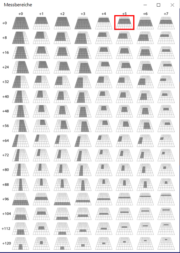
The measuring range determines what from the trapezoidal field of view of the scanner is used for measurement. By clicking on the question mark, the possibilities (see graphic below) are displayed and then the corresponding number is entered in the measuring range.

Measuring ranges DS925:
The next step is to make the settings for the encoder.
Mode: Selection between internal software encoder and external hardware encoder.
Expected speed: Expected speed of movement of the parts with software encoder.
Steps per line: Number of encoder steps per line of the scan. For DS900 software encoders, 4 should be set here.
Distance per cycle: Describes the travel distance of the axis for one revolution per step of the encoder.
Ignore encoder that is too fast: Select if an overflow error occurs when counting the encoder steps.

In the Miscellaneous section, you can set the time-outs of the scanner and activate the automatic arrangement of the cells.
Interpacket Timeout: Describes the time until timeout which may exist when two lines are recorded.
Transport Timeout: Describes the time that may elapse from the completion of the scan until the data is received.
Automatically arrange lines: Automatically sorts the lines of the scan.

The image acquisition can then be started. The sensor must be online for this.
Finished 3D image: