Cognex DSMax 3D Scanner
Operating the sensor in EasySightPro®
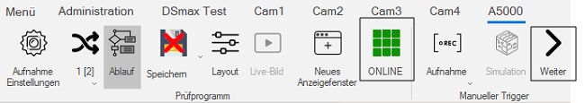
To inspect the scanner images, the station is assigned to the sensor and the associated program is selected.
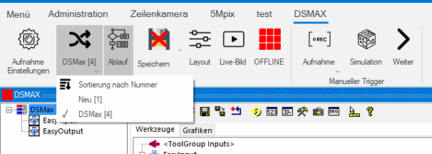
The program will now open the sequence:
Now the sensor can be set up. To do this, we start the setup wizard by clicking on the live image. The sensor must be offline for this.
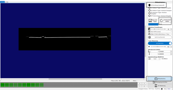
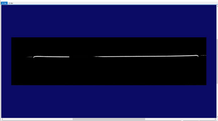
First, the test object should be brought into the measuring range of the sensor in the 2D setup. It appears there as a line (see image below). This is done in the Image Acquisition tab. Then the 2D setup is selected and the sensor is triggered continuously while the object is brought into the image. Note the working distance of the DSMAX of 55mm +/- 5mm.
The explanation of the symbols appears as soon as the cursor is placed over them.
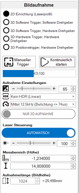
In the exposure settings, the exposure time can be adjusted. The edge of the object should be clearly visible, but not blurred and larger than real.
For objects with both good and bad reflective elements, the HDR mode can be switched on. This combines a short and a long exposure time into one image.
After the exposure time has been determined, the speed can be selected accordingly.

The laser control should be automatic for our purpose. If the laser is not switched on automatically, this control can be set to manual and the intensity can be adjusted by the controller.

Now the measuring range of the sensor can be set. The first value describes the starting height from the lower edge of the sensor measuring range. The second value indicates the measuring height upwards from the previously set value. The recording in targets gives the length of the scan and is at least 128 lines.
Now the encoder data can be parameterized. To do this, we call up the Motion setup tab:
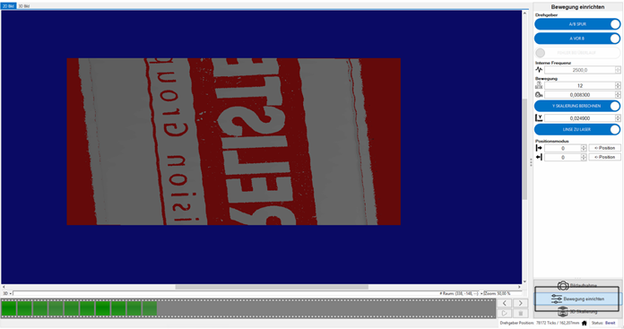
First the basic settings of the encoder type are made. At the top you switch between single and dual channel encoder. Then the counting direction of the encoder is determined. After that, an error message can be activated in case of an overflow.

Now we come to the settings for the clocking of the encoder. The internal frequency of the encoder is automatically obtained. If not, it can be entered here manually. Under the heading Motion you will first find the number of ticks per complete encoder cycle and the step size of a tick in mm. These data are to be taken from the encoder. If these values are not known, but the y-scaling is, this can be switched by a slider. In the field below the calculated scaling is output or the manual one is entered.
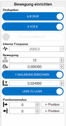
Finally for this menu the specifications for the positioning of the sensor are made.
By switching the controller, the direction of movement can be adapted to the orientation of the sensor.
In position mode, the system is active for an absolute number of lines. This can be useful if the same area is to be scanned constantly.

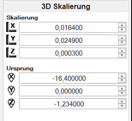
In the last menu 3D Scaling the scaling of the axes as well as the original position can be viewed and adjusted if necessary.
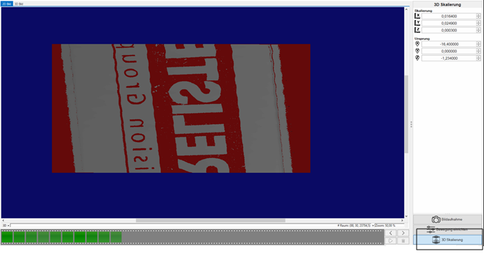
3D image of the sensor:
After completing the settings, the window can be closed.
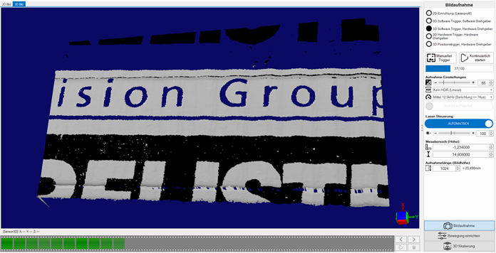
The image acquisition can then be started. The sensor must be online for this.
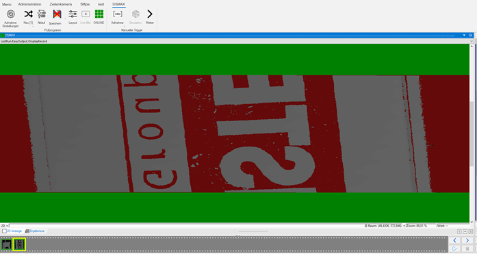
Finished 3D image in EasySightPro®: