Dalsa Linea Line Scan Camera
The Dalsa Linea line scan camera is parameterized in EasySightPro®ing the setup wizard. This takes over the correct configuration of all camera functions in the background.
Information: The assignment of the inputs and outputs can be found under Hardware/Cameras/Dalsa Linea.
Setting up the camera
The camera settings are automatically set by the setup wizard and do not have to be inserted in the program management. The setup wizard is started via the "Live Image" button of the respective camera station.
To set up, it is best to follow the menu sequence and set up as follows.
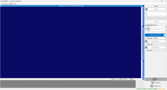
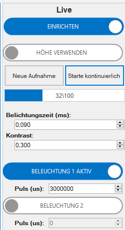
Menu "Live"
| Menu | Description |
|---|---|
| Setup | Activates the setup and thus bypasses the encoder parameters. The camera thereby picks out the lines with an internal frequency. |
| Reduce height | This sets the image height fixed to 100 lines to make the live image look smoother. |
| New acquisition | Captures 1 new image. |
| Start continous | Enables/disables a permanent live image. |
| Image counter | Indicates with a revolving counter that images are being captured. |
| Exposure | Exposure in milliseconds. The maximum exposure is 0.09ms. |
| Contrast | Brightness gain scaled from 0 - 1. 0 ... low image noise / dark image. 1 ... strong image noise / bright image |
| Illumination | Activates the corresponding lighting outputs. |
|
Pulse |
Pulse delay of the flash pulse in (microseconds). If the lighting is switched via an optocoupler, then the delay should not be less than the effective recording time. |
The image sharpness can be adjusted quite well by positioning the component under the camera and switching the camera to the continuous live image. This produces an image in which a complete vertical line is always displayed.
In this state, the image can be focused to maximum sharpness.
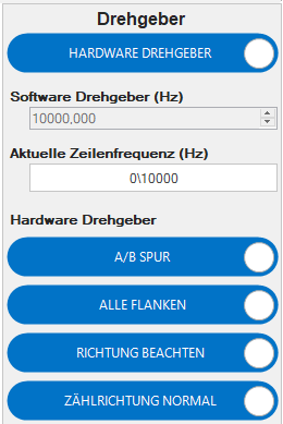
Menu "Encoder"
| Menu | Description |
|---|---|
| Hardware encoder | Switches between hardware encoder and software encoder. |
| Software encoder | Internal frequency of the software encoder. |
| Current line frequency | Current input frequency of the recording. If the counting direction is set incorrectly, the line frequency remains at 0 Hz during movement. |
| Use A/B | Encoder with A/B track or A track only. |
| All edges | Uses all edges or only the rising edge of the input signal. |
| Follow direction | Takes into account the counting direction of the encoder when using A/B. |
| Default counting | Normal or inverted counting direction. With this option the counting direction can be inverted. |
The first step is to set the encoder parameters before setting up the actual motion.
It is important that the "Current line frequency", when moving, shows a value > 0 Hz.
If the cabling of the encoder inputs and the counting direction is selected correctly, the current input frequency is displayed here.
After the encoder parameters are set correctly, the conversion of the encoder pulse to the image line is set. To facilitate this step, there is a setup guide for converting the encoder pulse to the correct camera parameters.
| Menu | Description |
|---|---|
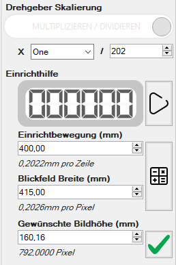
| Rotary encoder scaling | Conversion factors of the pulses to the corresponding camera lines. |
| Pulse counter | Internal camera pulse counter. Takes into account the parameters of the "Encoder scaling". |
| Set up Start | Starts the calibration process of the encoder. |
| Field of view width | Field of view width of the camera in mm. This value is required to achieve the most undistorted image possible in the direction of the encoder. |
| Calculate scaling | Calculates the best fitting scaling parameters based on the input data. |
| Setup movement | Movement of the encoder during the calibration process. |
| Desired image height | Adopts the field of view height in pixels as camera setting |
|
Take over field of view |
Adopts the field of view height in pixels as camera setting |
Calibration of the encoder should be performed as follows:
-
Move encoder/linear axis into position.
-
Press "Start setup".
-
Start setup movement.
The encoder/linear axis should be moved a known length.
-
Press "Stop setup".
-
Enter the length of the "setup movement" in millimeters.
-
"Calculate scaling"
Optionally, the required number of lines can be calculated:
-
Enter desired "field of view height" in millimeters.
-
"Take over field of view"
Menu "image acquisition"
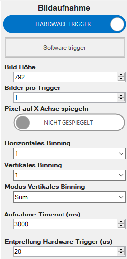
| Menu | Description |
|---|---|
| Hardware Trigger | Activates the hardware trigger. Alternatively, the software trigger (triggering controlled via EasySightPro®). |
| Software Trigger | Triggers a software trigger for test purposes. |
| Image height | Number of image lines. |
| Images per trigger | Number of images per trigger. If there is more than one image, they will be captured bump to bump without overlap. |
| Mirror pixel on X | Mirrors each row around the X axis. |
| Horizontal binning | Combines x horizontal pixels into one. The brightness is added up in the process. |
| Vertical binning | Combines x vertical pixels (lines) into one. The brightness is added up or averaged (depending on the mode). |
| Vertical binning mode | Behavior with vertical binning enabled. |
|
Acquisition Timeout |
Timeout from trigger to completion of the image. This parameter must be adjusted to the actual scanning process, otherwise the image acquisition will be aborted during the acquisition. |
|
Debouncing hardware trigger |
Debouncing of the hardware trigger in microseconds. |