Installation guide
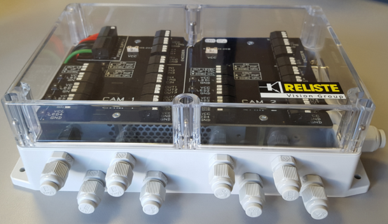
The EASY-CBOX is a universal connection box for industrial camera systems (2D, 3D, line scan cameras).
The connection of up to 2 independent cameras with up to 4 illuminations each is supported. The control electronics for fast lighting control directly via the camera is already included in the box.
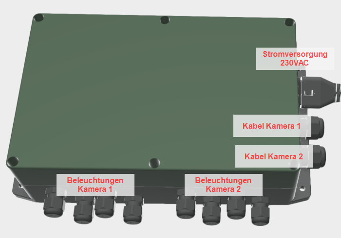
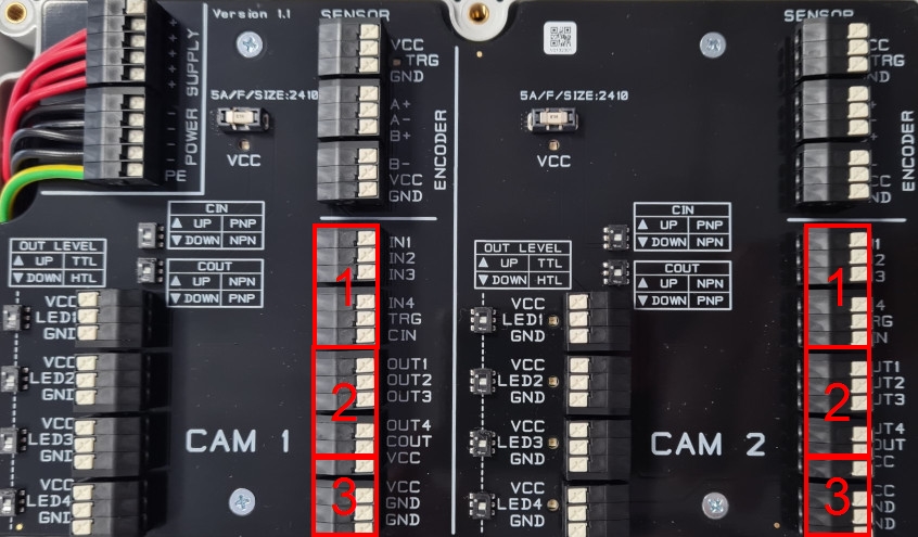
General view
Safety/warning instructions
Be sure to read the installation instructions before installing this product.
Warning:
Connection work may only be carried out by instructed persons or skilled workers. All connection work on the device may only be carried out when the device is in a de-energized state.It must be ensured that the devices and associated components are connected in accordance with the current laws, standards and regulations.Connection work may only be carried out with the tools intended for this purpose..
Use of the device for purposes other than those for which it is intended is prohibited.
If there is moisture in or on the device, the device must not be used..
Mechanical installation
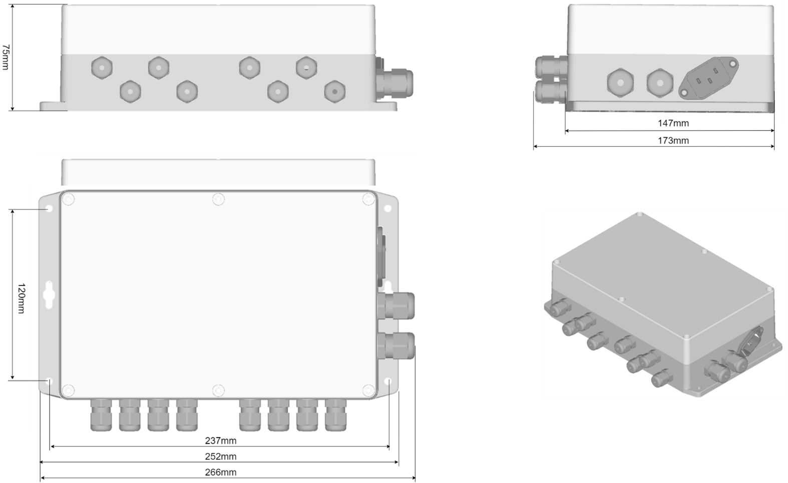
The EASY-CBOX is mounted via the 4 outer mounting holes (4 screws with diameter <= 4.5mm).
The installation site of the device must comply with the environmental conditions for operation.
Assembly work on the device may only be carried out when the device is de-energized.
It must be ensured that the devices and associated components are mounted in accordance with the current standards and regulations..
Assembly work may only be carried out with the tools intended for this purpose.
System wiring
Warning:
Before the device is connected to the supply network during commissioning, an acclimatization time of at least two hours must be taken into account, especially if the device is dewy due to temperature fluctuations.
If there is moisture in or on the device, the device must not be put into operation.The device is designed for operation on a rated supply voltage, before commissioning, check that this data is correct.
Information: Please refer to the documentation for the wiring of our camera systems
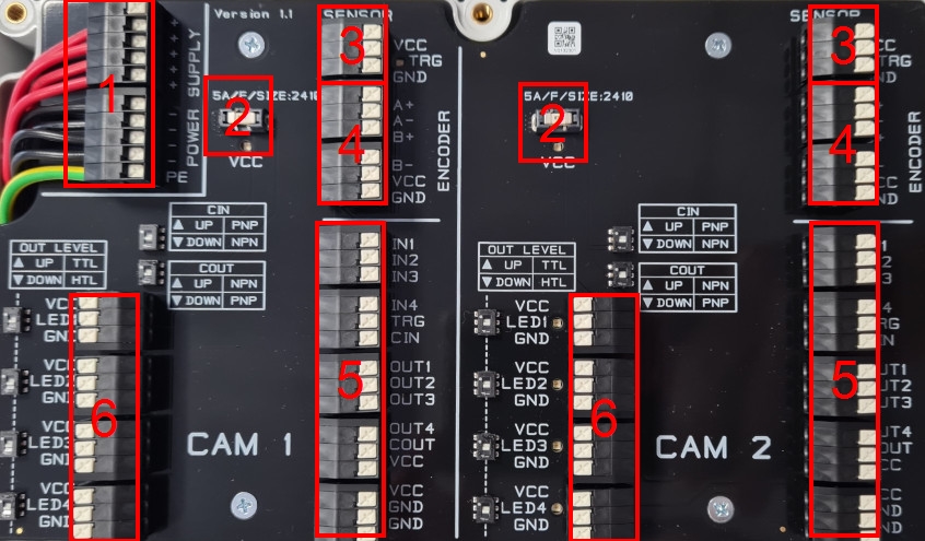
Terminal "Sensor" (3)
An external trigger sensor for the camera can be directly connected and also supplied via the "SENSOR" terminal.
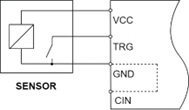
Sensor wiring depending on camera and CIN setting:
| CIN setting | Principle image |
|---|---|
| PNP (top) |
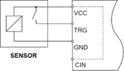
|
| NPN (bottom) |
|
Terminal"Encoder" (4)
An external encoder can be connected directly to the camera via the "ENCODER" terminal.
The connected camera must support the rotary encoder function!
Warning:
5VDC and 24VDC signal generators are supported, but only 24VDC signal generators may be supplied via the VCC terminal. 5VDC devices require an external supply!
Improper connection can lead to a defect of the device.
The internal wiring of the signals looks as follows:
| Encoder | CAM1/CAM2 | Comment |
|---|---|---|
| A+ | IN1 | Internally connected |
| A- | IN2 | Internally connected |
| B+ | IN3 | Internally connected |
| B- | IN4 | Internally connected |
| VCC | 24VDC | |
| GNC | GND |
Terminal CAM1/CAM2 (5)
The camera is connected to the EASY-CBOX via the "CAM1" / "CAM2" terminal using the IO cable. For each camera model, input/output wiring with the corresponding potential can be set separately.
Warning:
The input and output potentials of the camera must be set correctly.otherwise it may cause damage or malfunction of the hardware.
Ex works the potentials are set to PNP and HTL.
Only cameras that are designed for operation with 24VDC may be supplied via the VCC/GND terminal.!
Connection camera IO cable
| Block | Terminal | Comment |
|---|---|---|
| Inputs camera | IN1 | Input 1 |
| IN2 | Input 2 | |
| IN3 | Input 3 | |
| IN4 | Input 4 | |
| TRG | Internally connected with terminal „SENSOR“ – „TRG“ | |
| CIN | COMMON input (potential via CIN) | |
| Outputs camera | OUT1 | Output 1 |
| OUT2 | Output 2 | |
| OUT3 | Output 3 | |
| OUT4 | Output 4 | |
| COUT | Output COMMON (potential via COUT) | |
| Supply camera | VCC | Supply +24VDC |
| GND | Supply GND |
Logic for camera inputs (CIN)
The logic for camera 1 + 2 can be set here at separately from each other.
| Switch CIN | Switching signal coming from camera | Comment |
|---|---|---|
| NPN (top) | GND | Negative input logic |
| PNP (bottom) | 24VDC | Positive input logic |
Logic for camera outputs (COUT and OUT LEVEL)
The logic for camera 1 + 2 can be set here at separately from each other.
The switching potential is set via "COUT" and the switching level of the outputs via "OUT LEVEL".
| Switch COUT | Switching signal coming from camera | Comment |
|---|---|---|
| NPN (top) | 24VDC | Negative input logic |
| PNP (bottom) | GND | Positive input logic |
| OUT LEVEL | Logical 1 | Logical 0 |
|---|---|---|
| TTL (top) | >4,3V@>10mA (Max 6V) | <0,8V |
| HTL (bottom) | >19,3V@>10mA (Max 33V) | <1,0V |
Terminal "LED1-4" (6)
External lighting can be controlled directly via the EASY-CBOX using the "LED1-4" terminals. The control signal comes directly from the camera via the terminals "OUT1" to "OUT4"..
Information: Only PNP switching lights are supported!Maximum output current per light: 9A for 10ms or 5A continuous!
Warning: Maximum current consumption via the integrated power supply of 5A continuously over all 8 outputs.
| Terminal | Comment |
|---|---|
| VCC | >4,3V@>10mA (Max 6V) |
| LED1 | >19,3V@>10mA (Max 33V) |
| LED2 | >19,3V@>10mA (Max 33V) |
| LED3 | >19,3V@>10mA (Max 33V) |
| LED4 | >19,3V@>10mA (Max 33V) |
| GND | Supply GND |
Integrated power supply
The EASY-CBOX has an integrated power supply unit that is supplied externally with 230VAC via the IEC plug..
| Output voltage: | 24VDC ±1% |
| Output current: | 6,2A @(-20…+40°C) permanent 8,75A@(-20…+40°C) for 100ms |
| Efficiency: | 92% |
| MTBF: | 155 000h according to MIL-HDBK-217F at +25 °C |
| Protection: | Short-circuit protection: shutdown with automatic restart
Overload protection: At 140% typ., shutdown with automatic restart Overvoltage protection: Switch off |
| Standby consumption: | <0.5W@0A load |
Maintenance
There are no parts in the device that require maintenance.
Cleaning
Before carrying out any cleaning work on the device, disconnect all poles of the device from the power supply.
The device must not be exposed to splashing, dripping or gushing water.
The device may only be cleaned with the aid of damp, non-scratching, solvent-free and chemical-free cleaning cloths..
Cleaning water must not get to the electrical and electronic components.
Opening the device for cleaning purposes is prohibited.
Repair/Exchange
The device may only be replaced when the device is in a de-energized state.
If fire or its accompanying phenomena (for example, lightning and smoke) are associated with the device, disconnect all poles of the device from the voltage sources.
Before exchanging, replacing or inserting the fuses, all poles of the device must be disconnected from the supply voltage..
The device may only be repaired by the manufacturer.
Disassembly
Disassembly of the device may only be performed when the device is in a de-energized state.
The device may only be disassembled using the tools intended for this purpose.
Recycling
The devices contain electronic components and therefore represent hazardous waste, for this reason they must be delivered to a designated collection point.
Technical key data
| Supply voltage | |
|---|---|
| Rated supply voltage | 230VAC |
| Supply voltage range | 90..264Vac |
| Frequency range of the supply voltage | 47..63Hz |
| Energy consumption | <170W |
| Duty cycle | 100% |
| Protective conductor current | <0,65mA@250Vac;63Hz |
| Recommended fuse | Sicherungsautomat (IE C 60898-1): In: max. 10A C-Charakteristik |
| Overvoltage category | 2 |
| Max. recommended cable length | 30m |
| Digital inputs | |
|---|---|
| 24VDC digital input without galvanic isolation | 2 x 4 |
| Voltage | TTL: 5V
HTL: 24V |
| Voltage upper limit | TTL: 6V HTL: 33V |
| Level for logic 0 | TTL: <0,8V HTL: <1,0V |
| Level for logic 1 | TTL: >4,3V@>10mA
HTL: >19,3V@>10mA |
| Input current | TTL: <23mA@5,0V
HTL: <13,5mA@24,0V |
| Max. recommended cable length | 30m |
| Outputs (illuminations) | |
|---|---|
| Semiconductor output
(normally open) without galvanic isolation to input and supply 24Vdc |
2 x 4 |
| Voltage drop between voltage output | 1mA / 5Vdc |
| Switching current per output | <9A@+25°C; <10ms |
| Continuous current per output (with one external supply) | <5A |
| Continuous current for all outputs (with one internal supply) | <5A |
| Switching cycles | unlimited |
| Delay times input (10%) to output (90%) - with push-pull driver | ON: <1ms
OFF: <1ms |
| Delay times input (10%) to output (90%) - with open collector driver | ON: <1ms
OFF: <15ms |
| Max. recommended cable length | 30m |
| Power supply camera 1 & 2 | |
|---|---|
| Voltage (CAM1, CAM2) | 24Vdc, +/-1% |
| Rated current per camera | <=5A@+25°C
<=4,8A@+50°C |
| Fuse (CAM1, CAM2) | Size 2410, In: 5A, Characteristic: F Type: Littelfuse/0453005 |
| Fuse tripping current | >=9A@100ms |
| Total current of outputs CAM1 + CAM2 | >=9A@100ms |
| Type of extra-low voltage | PELV |
| Mechanics | |
|---|---|
| Mechanical dimensions | 266 x 173 x 75 mm |
| Weight | 500g |
| Mounting | 4 screws <= 4,5mm diameter |
| Mounting position | Wall: IEC 60320 coupling right Bottom: Front panel top |
| Terminals | |
|---|---|
| Type | Spring clamp |
| Clamping capacity conductor | 1x 0,2 - 1,5mm²
1x AWG24 - 16 |
| Stripping length | 9-10mm |
| Lifetime | |
|---|---|
| MTBF | <150.000h@+25°C |
| Environmental conditions | |
|---|---|
| Ambient temperature (operating) | -20° to 50 °C |
| Relative humidity (operating) | 5 - 85% |
| Ambient temperature (storage) | -40° to 85 °C |
| Relative humidity (storage) | 10 - 90% |
| Protection class | Housing IP40 |
Product marking
|
|
This product complies with EU regulations. |
|
|
This product must not be disposed of with household waste. |