Configuration for Baumer VCXG
| IO cable: | 1x M8 8 pole |
|
| Supply: | 24VDC via EASY-CBOX | |
| Inputs: | 1 (PNP, HTL) | |
| Outputs: | 1 (PNP, HTL) | |
| 2 GPIO (max. 3.3V TTL) | ||
| Digital trigger: | is supported | |
| Rotary encoder: | - | |
| Illuminations: | max. 3 illuminations via 1x output and 2x GPIO |

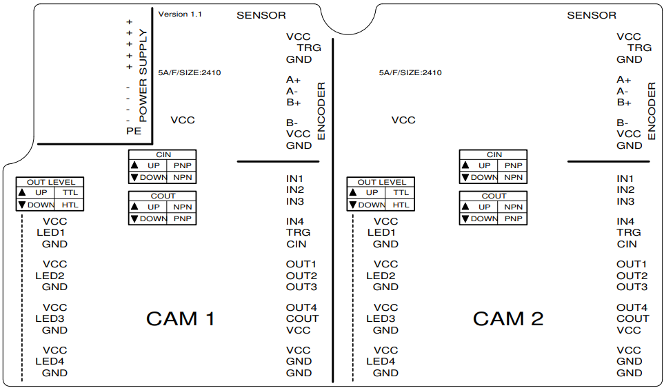
Switch positions on circuit board
| Switch | Position | Comment |
|---|---|---|
| CIN | PNP (top) | Positive input logic |
| COUT | PNP (bottom) | Positive output logic |
| OUT LEVEL - LED1 | HTL (bottom) | Out 1 (Line3) |
| OUT LEVEL - LED2 | TTL (top) | GPIO (Line 1) |
| OUT LEVEL - LED3 | TTL (top) | GPIO (Line2) |
| OUT LEVEL - LED4 | - | not used |
IO cabling on EASY-CBOX
Information: ALL GPIO's are wired as outputs in this example
| Camera IO cable | EASY-CBOX | ||
|---|---|---|---|
| Pin | Function | Color | Terminal |
| 1 | GPIO (Line2) | White | CAM - OUT3 |
| 2 | Power VCC | Brown | CAM - VCC |
| 3 | IN1 (Line0) | Green | CAM - TRG |
| 4 | GND IN1 | Yellow | CAM - CIN |
| 5 | Power VCC Out1 | Grey | CAM - COUT |
| 6 | OUT1 (Line3) | Pink | CAM - OUT1 |
| 7 | GND (Power, GPIO) | Blue | CAM - GND |
| 8 | GPIO (Line1) | Red | CAM - OUT2 |