EthernetIP Adapter
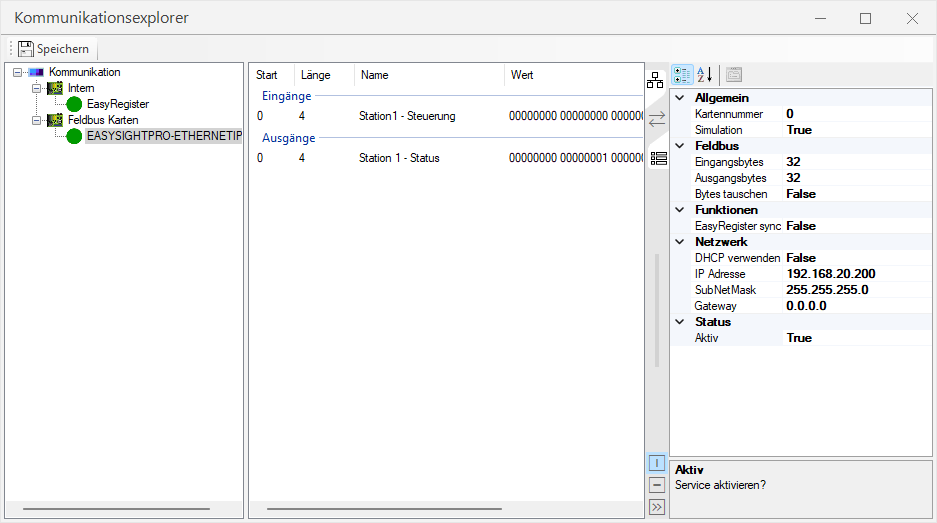
The communication parameters are adjusted in the communication explorer.
To do this, select the corresponding fieldbus card on the left in order to then be able to make the corresponding settings in the right part of the communication explorer.
Information: Make sure that the corresponding communication module is loaded.
| Setting | Value |
|---|---|
| Common: Card number | ID of the fieldbus card for which these settings apply. |
| Common: Simulation | Here you define whether the fieldbus card is to be simulated. This enables the test operation of the interface without existing fieldbus card. |
| Fieldbus: Input bytes | Size of the input area in bytes after initialization of the interface. |
| Fieldbus: Output bytes | Size of the output area in bytes after initialization of the interface. |
| Fieldbus: Swap bytes | Here you specify whether the order of the bytes on the entire interface is to be swapped. The default byte order is big-endian, for little-endian swapping must be enabled. |
| Functions: EasyRegister synchronize | Sets once the names and data types of all used EasyRegister transfers in the EasyRegisters. |
| Functions: EasyRegister synchronize | Sets once the names and data types of all used EasyRegister transfers in the EasyRegisters. |
| Network: IP address | Sets a static IP address if DHCP is disabled. |
| Network: SubNetMask | Sets the SubNet mask when DHCP is disabled. |
| Network: Gateway | Sets the gateway when DHCP is disabled. |
| Status: Active | Here you define whether the fieldbus card should be activated or not. |
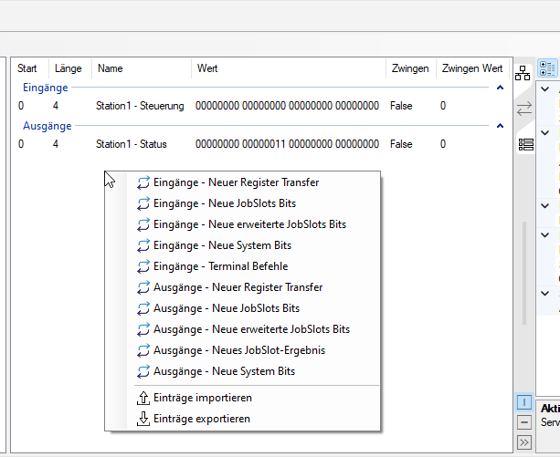
In the middle part of the communication explorer, you can now add individual fieldbus blocks by right-clicking, or edit or delete existing ones.
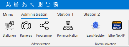
You can access the monitoring and status check via the Administration menu..
Here the status and values of the inputs and outputs of the EthernetIP communication can be monitored.
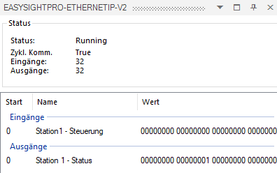
The status of the communication between EasySightPro® and the external control via EthernetIP is displayed. Here you can see if there is a connection to the external control.
After that, the size of the available input and output area is displayed.
The assignment, naming and current values of the parameterized inputs and outputs follow below.
The window can be pinned and thus remains visible.